Additional data: calibration step
Extrinsic parameters
The position and orientation of the sensors have been measured manually. Sensor coordinate frames are relative to the vehicle frame origin. The vehicle frame is such that its origin is in the middle of the back rear axle, the X axis is horizontal in the ongoing direction, the Z axis is vertical and the Y axis is confounded with the rear axle, completing the direct frame. The numerical values of those transforamtions are given with a right-handed "RPY" Euler angle parametrization of SO3 using a fixed axis interpretation, in [ X Y Z Roll Pitch Yaw ] format. All rotations are in radians and translations are in meters.The rough values of the extrinsic parameters are listed below.
| Sensor | Alias | Estimated transformation | |
|---|---|---|---|
| Forward left camera | f-l-cam | [1.525 0.25 1.665 -π/2 0 -π/2]T | |
| Forward right camera | f-r-cam | [1.525 -0.25 1.665 -π/2 0 -π/2]T | |
| Backward camera | b-cam | [-0.325 0.1 1.67 π/2 0 -π/2]T | |
| Forward middle camera | f-m-cam | [1.5 0 1.665 -π/2 0 -π/2]T | |
 |
Catadioptric camera | cata-cam | [0.595 -0.05 3.04 -π/2 0. 0.]T |
| Fisheye camera | fe-cam | [1.505 0.100 1.84 -π/2 0 -π/2]T | |
| Webcam | webcam | [1.55 0 1.80 -π/2 0 -π/2]T | |
| Horizontal laser | hz-laser | [1.595 0 0.22 -π/2 0. 0.]T | |
| Inclined laser | incl-laser | [1.505 0.1 1.965 -π/2 0. -20.*π/180]T | |
| RTK GPS | r-gps | [0. 0 1.81 0. 0. 0.]T | |
| Low-cost GPS | l-gps | [0. 0.1 1.81 0. 0. 0.]T | |
| Accelerometer | acc | [0. 0. 0.56 π π 0.]T | |
| 1D gyrometer | gyro | [0. 0. 0.56 π π 0.]T | |
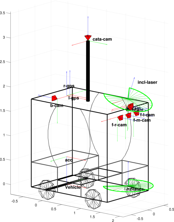
The poses of the forward left and right cameras have been estimated using the approach proposed in [Lebraly12]. Rotations are very accurate while the scale factor has been manually estimated for the translations:
| Sensor | Alias | Estimated transformation | |
|---|---|---|---|
| Forward left camera | f-l-cam | [1.6252 0.2450 1.7100 -1.5534 0.0002 -1.5890]T | |
| Forward right camera | f-r-cam | [1.6252 -0.2450 1.7100 -1.5591 -0.0019 -1.5746]T | |
Intrinsic parameters of the visual sensors
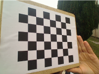
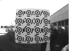
For each camera, images of two planar calibration patterns have been acquired. One pattern contains circular landmarks with a black bullseye and a circular code. These landmarks guarantee a subpixel detection. An automatic feature detector allows to accurately estimate the landmarks’ center and their label. The second pattern is a classical chessboard.| Chessboard | Pattern with circular targets |
 |
 |
| Pattern dimensions | Pattern dimensions / Pattern with labelled targets |
| Sensor | Alias | Model | Intrinsic parameters | Reproj. error |
|---|---|---|---|---|
| Forward left camera | f-l-cam | Pinhole + dist. | [fu fv u0 v0]=[1047.34 1047.93 512.97 382.36] kc=[-0.254 0.144 -0.000 -0.000 -0.080] |
[0.233 0.185]T |
| Forward right camera | f-r-cam | Pinhole + dist. | [fu fv u0 v0]=[1042.75 1042.84 516.13 391.74] kc=[-0.251 0.122 -0.000 -0.000 -0.039] |
[0.357 0.306]T |
| Backward camera | b-cam | Pinhole + dist. | [fu fv u0 v0]=[1047.83 1048.14 499.70 398.48] kc=[-0.263 0.170 0.000 0.000 -0.107] |
[0.247 0.182]T |
| Forward middle camera | f-m-cam | Pinhole + dist. | [fu fv u0 v0]=[650.57 650.98 511.63 387.90] kc=[-0.348 0.144 -0.000 0.000 -0.030] |
|
| Catadioptric camera | cata-cam | Model on the sphere | [fu fv u0 v0]=[359.86 360.08 670.96 458.77] ξ=1 |
|
| Fisheye camera | fe-cam | Model on the sphere | [fu fv u0 v0]=[1308.37 1302.10 688.07 470.88] ξ=1.723 |
[0.163 0.155]T |
| Webcam | webcam | Pinhole + dist. | [fu fv u0 v0]=[534.81 530.44 330.27 222.44] kc=[0.051 -0.183 -0.000 -0.000 0.088] |
[0.223 0.195]T |
- Pinhole + dist. projection model
The skew is supposed to be equal to 0. Tangential distortions and radial distortions up to the 5th degree are considered. - Model on the sphere
The skew is supposed to be equal to 0. Tangential and radial distortions are set equal to 0. - Reprojection error: "Pixel error" [err_std(1) err_std(2)]T
Sequences for calibration
If the user uses a different projection model or wants to calibrate himself the camera, we provide images of the patterns (refer to the page Downloads).Reprojection
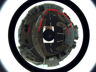
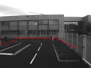
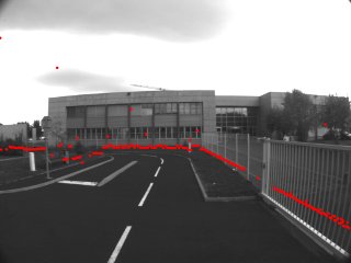
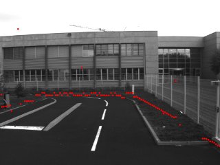
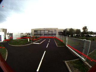
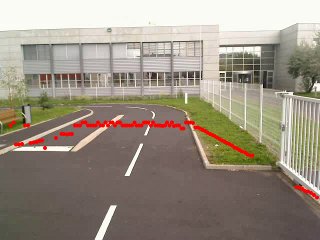
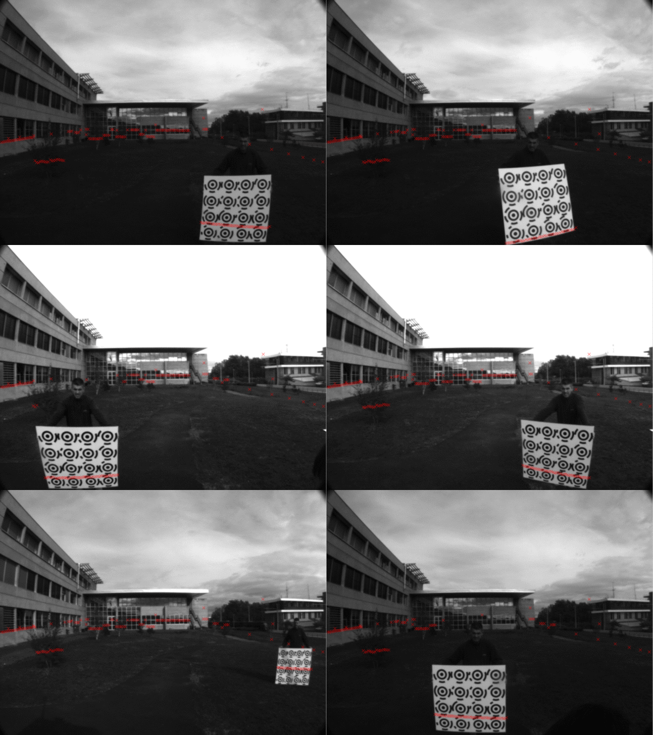
Reprojection of the impacts detected by the horizontal range-sensor in the images from the different sensors using the transformations and intrinsic paramaters of the cameras provided above.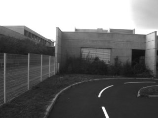
Laser-camera calibration
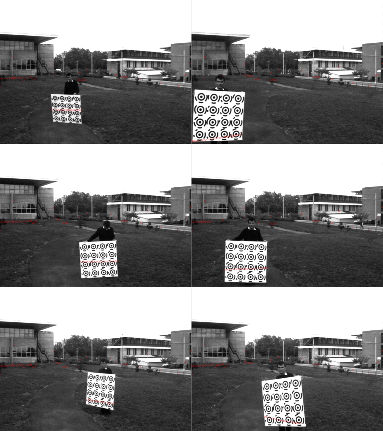
The RADLOCC Laser-Camera Calibration toolbox has been used ([Kassir10]; website). We carefully follow the advices from the toolbox authors. Changes to the background remain as minimal as possible. The calibration board has not been rotated more than 45 degrees about its orthogonal axis. Finally, the board's position was moved around as much as possible throughout the dataset. The camera calibration provides the orientation and position of the calibration plane (using as for camera calibration a pattern with circular landmarks with a black bullseye and a circular code).Warning: the frame coordinates are different between our work and RADLOCC. The transformation between the camera and the laser is obtained as follow:

where Δ is the translation offset and Φ is the rotation matrix as defined in RADLOCC, the second matrix beeing the coordinates transformation.
The following transformations have been found:
| Transformation | Uncertainty on Delta | Uncertainty on Phi(deg) | Total rms error | |||||||||||||||||
|---|---|---|---|---|---|---|---|---|---|---|---|---|---|---|---|---|---|---|---|---|
| f-m-camThz-laser |
|
[0.0104 0.0275 0.00508] | [13.5 0.115 13.8] | 0.00748 | ||||||||||||||||
| f-m-camTincl-laser |
|
[0.0172 0.0746 0.0101] | [61.6 0.348 61.8] | 0.00817 | ||||||||||||||||
| f-l-camThz-laser |
|
[0.045 0.203 0.0199] | [21.3 2.36 20.8] | 0.00871 | ||||||||||||||||
| f-r-camThz-laser |
|
[0.0802 0.385 0.0382] | [20 1.79 21] | 0.00878 |
| Forward left camera | Forward middle camera |
 |
 |
Sequences for calibration
Images and RADLOCC-like structures are provided.Proprioceptive sensors
Odometer + steering angle
Some sequences have been acquired driving the vehicle at constant velocity and steering angle. DGPS data are provided.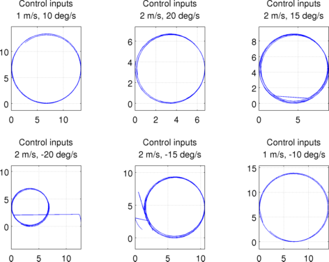
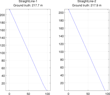
We provide also 2 sequences with the vehicle droved in a straight line. The total length of the paths have been measured with a measuring wheel.
Accelerometers
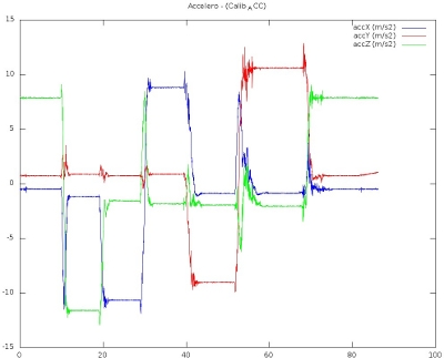
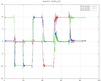
The intrinsic calibration of the accelerometers have been done. We supposed that the acceleration (accx for instance) is a linear function of the raw value:
To estimate the parameters, we moved the accelerometers such that the gravity is aligned with each axis some seconds.
| Before calibration | After calibration |
 |
 |
| accx | accy | accz | |||
|---|---|---|---|---|---|
| kaccx | 1610.0 | kaccy | 1622.4 | kaccz | 1610.6 |
| offset_accx | 0.935 | offset_accy | -0.767 | offset_accz | 1.876 |
Citations
- [Lebraly12] P. Lébraly. Étalonnage de cameras à champs disjoints et reconstruction 3D - Application à un robot mobile. Thèse de l'Institut Pascal (CNRS - Université Blaise Pascal), January 2012
- [Kassir10] Kassir, A. and Peynot, T. Reliable Automatic Camera-Laser Calibration. In Australasian Conference on Robotics and Automation, 2010