
Logs format
The data of each interface are saved in a folder called
List of ID_INTERFACE :
We also provide other data that have been logged. For instance, they have been obtained by fusing data from multiple sensors (dead-reckoned pose using motor odometry and steering angle data ...). | Sensor | Alias | |||
|---|---|---|---|---|
| Forward left camera | f-l-cam | Bus_InterfaceCamera_2672909685359666 | ||
| Forward right camera | f-r-cam | Bus_InterfaceCamera_2672909685359667 | ||
| Backward camera | b-cam | Bus_InterfaceCamera_2672909685359670 | ||
| Forward middle camera | f-m-cam | Bus_InterfaceCamera_2892819404705840 | ||
| Catadioptric camera | cata-cam | Bus_InterfaceCamera_13602058368439990 | ||
| Fisheye camera | fe-cam | Bus_InterfaceCamera_13602058368474999 | ||
| Webcam | web-cam | Bus_InterfaceCamera__dev_video0 | ||
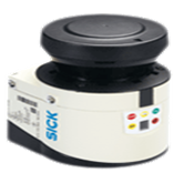
| Horizontal laser | hz-laser | Bus_InterfaceRangefinder_172_27_30_21_2112 | ||
| Inclined laser | incl-laser | Bus_InterfaceRangefinder_172_27_30_31_2112 | ||
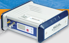
| RTK GPS | rtk-gps | Bus_InterfaceGps__dev_ttyM0 | ||
| Low-cost GPS | lc-gps | Bus_InterfaceGps__dev_ttyACM0 | ||
| Bus_InterfaceCan_can0 | ||||
Visual sensors - Range sensors - GPS sensors - Proprioceptive sensors - Other data

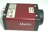
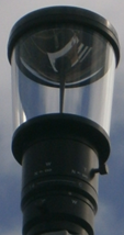
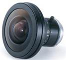
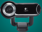 VISUAL SENSORS
Images and timestamp
The file| line | Associated files | ||||
| #1 (header) | Version |
|
| | ||
| → | |||||
-
Rtime is the reception time expressed in microseconds from the beginning of the acquisition -
latency is the camera latency, expressed in microseconds - the image number
num is the line number plus one, with 10 digits length - the file extension
extension is pgm (case of the firewire camera when images are in gray-level) or ppm (case of the color cameras)
Sample for camera of id
| Bus_InterfaceCamera_2672909685359666.dates | Associated files | ||||
|---|---|---|---|---|---|
| Version 1 121558 121558 0 255049 255049 0 388331 388331 0 → |
| ||||
 |
 |
 |
 RANGE SENSORS
Range sensor impacts and timestamp
The file| line | Associated files | ||
| #1 (header) | Version XXX | ||
| → |
| line | ||
| #1 (header) | ||
Rtime is the reception time expressed in microseconds from the beginning of the acquisitionnumlay is the number of the layer. LMS151 sensors have only one layer.numimpacts is the number of impactsangle is the angle of the scan, expressed in radiansdistance is the distance to the impact, expressed in meters. A distance of zero means that there is no impact in the range of distance of the sensor.
Sample for range sensor of id
| Bus_InterfaceRangefinder_172_27_30_21_2112.dates | Associated files | ||||
|---|---|---|---|---|---|
| Version XXX 191 193478 213493 → |
| ||||
| 541 -0.785398 0.135 -0.776672 0.115 -0.767945 0.113 -0.759218 0.092 |
541 -0.785398 0.14 -0.776672 0.126 -0.767945 0.112 -0.759218 0.113 |
541 -0.785398 0.115 -0.776672 0.127 -0.767945 0.123 -0.759218 0.107 |
 GPS sensors
3D location and accuracy data
These data are provided by the essential fix data from GGA sentence (refer to http://www.gpsinformation.org/dale/nmea.htm#GGA). These data have been processed to give a file (| line | |||||||||||||
Details:
Rtime is the reception time expressed in microseconds from the beginning of the acquisition- Two coordinates are used for GPS positions: WGS84 (_wgs) and Lambert2IIe (_l2e).
lat andlng are the latitude and longitude, expressed in radians for WGS84 coordinates and in meters for Lambert2IIe coordinates.alt is the sum of the altitude above mean sea level (ellipsoidal height) and the height of geoid above ellipsoid, expressed in meters.
In our experiments, the height of geoid (mean sea level) above WGS84 ellipsoid is equal to 50.090 for the RTK-GPS and 47.4 for the UBlox. nb_sat is the number of satellites being trackedutc_time is the UTC time when data is taken, expressed in the format YYYYMMDD (as in the GGA sentence).fix_quality is the fix quality (2 = DGPS fix for the UBlox and 4 = Real Time Kinematic for the RTK-GPS)HDOP is the horizontal dilution of positionage_corr_diff is the time in seconds since last DGPS update
Sample for GPS sensor of id
| Bus_InterfaceGps__dev_ttyACM0_GGA_all.txt | |
|---|---|
| 476121 660168.799340458 2084722.75496854 460.600012207031 0.798665417515059 0.0542784685555518 460.600012207031 8 32322 2 0.980000019073486 -1 1475353 660168.786374253 2084722.75484107 460.600012207031 0.798665417515059 0.0542784656466697 460.600012207031 8 32323 2 0.980000019073486 -1 2473341 660168.786191338 2084722.77336542 460.699987792969 0.798665420423941 0.0542784656466697 460.699987792969 8 32324 2 1.25 -1 |
Tracks files
Additionnaly, we provide the trajectory in GPX and KML formats (track) in the files
For the GPX file, the schema version 1.1 is used (http://www.topografix.com/GPX/1/1/). In
Show example
Sample for GPS sensor of id
| Bus_InterfaceGps__dev_ttyACM0_GPX.gpx | |
|---|---|
| <?xml version="1.0" ... ... <trk> <trkpt lat="45.76015767" lon="3.109927167"> <ele>460.6000122</ele> <fix>2</fix> <sat>8</sat> <hdop>0.9800000191</hdop> <ageofdgpsdata>-1</ageofdgpsdata> </trkpt> ... </xml> |
Satellites in View
Data about the satellites that the unit might be able to find are extracted from the GSV sentences (refer to http://www.gpsinformation.org/dale/nmea.htm#GSV) and are given in the file| line | |||||||||
| ... | |||||||||
Details:
Rtime is the reception time expressed in microseconds from the beginning of the acquisitionnb_sat_data is the number of satellites with available GSV dataidcanal is the satellite PRN numberel is the elevation angle, expressed in degreesaz is the azimuth angle, expressed in degreesSNR is the Signal to Noise Ratioidcanal ,el ,az andSNR are given for each (possible) 12 satellites.
Sample for GPS sensor of id
| line | Bus_InterfaceGps__dev_ttyACM0_GSV.txt |
|---|---|
| 476606 11 3 2 0.453785598278 0.907571196556 40 12 0.558505356312 1.53588974476 39 14 0.331612557173 3.92699074745 38 0 0 0 0 0 0 0 0 0 0 0 0 0 0 0 0 0 0 0 0 0 0 0 0 0 0 0 0 0 0 0 0 0 0 0 0 476850 11 3 25 1.20427715778 1.1344640255 40 29 1.46607661247 3.35103225708 40 30 0.209439516068 5.02654838562 25 0 0 0 0 0 0 0 0 0 0 0 0 0 0 0 0 0 0 0 0 0 0 0 0 0 0 0 0 0 0 0 0 0 0 0 0 476975 11 3 33 0.593411922455 3.57792496681 35 39 0.575958669186 2.61799383163 34 40 0.296705961227 2.07694172859 65535 0 0 0 0 0 0 0 0 0 0 0 0 0 0 0 0 0 0 0 0 0 0 0 0 0 0 0 0 0 0 0 0 0 0 0 0 |
NMEA sentences
For persons that are accustomed to processing directly the NMEA sentences, those sentences are listed in the file| line | |||||
| #1 (header) | Version XXX | ||||
Details:
sentence_type is the type of sentence: GGA or GSVnumchar is the number of characters in the fileID_INTERFACE .txtRtime' is the reception time expressed in hour:minute::second.microseconds from the beginning of the acquisitionlatency' is the latency, expressed in hour:minute::second.microseconds
 Proprioceptive sensors
Multiple proprioceptive sensors are put on the vehicle: motor encoder, steergin angle encoder, right and left wheels encoders, accelerometers and a magnetometer. For those sensors, both estimated data (using estimated parameters) and raw data are provided.Motor encoder
| line | |||||||
transl_vel is the translationnal velocity, expressed in m/sdistance_odo is the estimated distance travelled by the robot, expressed in m- These elements are computed using the following formula:

According to the datasheet, the speed encoder has a resolution of 0.001 m/s thus we set kspeed = 1./(0.001). (64 is the number of tops by revolution)
The diameter of the wheel (wheel_diameter) is 49cm (but depends on the pressure of the wheel), the motor_ratio is 1/9.9 thus the travelled distance is k_distance_odo=0.0024 m.
direction is the direction of the vehicle:- 0: the vehicle is at rest
- 1: the vehicle is moving forward
- 2: the vehicle is moving backward
raw_speed is the speed measured by the motor odometry. We supposed that the translationnal velocity is proportionnal to the raw value:

The value of the parameter according to the datasheet is: kspeed=1./(0.001)(resolution 0.001 m/s)
For our sensor, we estimate those values to be:kspeed 1095. raw_odom is the value of the motor encoder counter. We supposed that the distance travelled by the vehicle is proportionnal to the raw value.
The value of the parameter according to the datasheet is: kodom=1./(0.001)(resolution 0.001 m/s)
The sensor gives us 128 "top" per motor revolution, and behind one reducer of 1:9.9 and with wheels about 40 cm in diameter, this represents approximately 1mm per "top" (0.40 * 3.14/9.9/128) - Specific calibration datas (see [calibration]) helped us to specify the value of 1.095 mm/top
Steering angle encoder
| line | ||||||
steering_angle is the steering angle, expressed in radiansrawsteering_angle is the steering angle encoder value (int16_t). We supposed that the steering angle is a linear function of the raw value:

The values of the parameters according to the datasheet are: kangle=1./(60.*π/180.0/32768.)(-60deg < steering_angle (deg) < +60deg; resolution of 0.002deg) and offset_angle=0.
For our sensor, we estimate those values to be:kangle 31060. offset_angle -0.004
Wheel encoders
| line | |||||||||||
Details:
speed_right is the speed of the right rear wheel, expressed in rad/sdist_right is the distance travelled by the right rear wheel, expressed in metersspeed_right anddist_right are computed using the following formula:
 (128 is the number of tops by revolution)
We suppose that kspeed as a resolution of 0.001 m/s and the diameter of the wheel (wheel_diameter) is 49cm (thus the resolution is approximately of 1cm).
speed_left anddist_left are data for the left rear wheel.
Accelerometers
| line | |||||||||||
Rtime is the reception time expressed in microseconds from the beginning of the acquisitionaccX ,accY andaccZ are the estimated values of the accelerations expressed in m/s2 in the sensor frameacc1 ,acc2 andacc3 are the estimated values of the accelerations expressed in m/s2 in each direction separatlyraw_acc1 ,raw_acc2 andraw_acc3 are the raw values of the accelerations measured by the accelerometers (encoded in uint16_t; 65536 values). We supposed that the acceleration (accx for instance) is a linear function of the raw value:

The values of the parameters according to the datasheet are: kacc1=kacc2=kacc3=1./(2*20.20125/65536.) and offset_acc1=offset_acc2=offset_acc3=0 (null offset and -20.20125 < acc (m/s2) < +20.20125). For our sensor, we estimate those values to be:acc1 acc2 acc3 kacc1 1610.0 kacc2 1622.4 kacc3 1610.6 offset_acc1 0.935 offset_acc2 -0.767 offset_acc3 1.876
Gyrometer
| line | |||||
Rtime is the reception time expressed in microseconds from the beginning of the acquisitionwz is the estimated value of the angular velocity, expressed in rad/stemp is the estimated value of the temperature, expressed in deg Celsus.raw_wz is the raw value of the angular velocity measured by the gyrometer (encoded in uint16_t). The estimated value is computed using the following formula:

According to the datasheet, -93.75deg/s < wz (deg/s) < 93.75deg/s and rawwz is encoded by 2 bytes (65536 values) thus we set k_wz=1./(187.5π/180./65536.) and offset_wz=-93.75π/180.raw_temp is the raw value of the temperature measured by the gyrometer (encoded in uint16_t). The estimated is computed using the following formula:

The values of the parameters according to the datasheet are k_temp=1./(500./65536.) and offset_temp=-225.0 (null offset and -225 degC < temp (degC) < +275 degC)
Other data
Dead-reckoning from odometry
The 2D positions and orientations of the vehicle are dead reckoned using knowledge about a vehicle's course and speed over the period of time using the motor and steering angle data (file| line | ||||
Details:
- [
x ;y ]T is the position of the vehicle estimated using odometry data, expressed in meters. When the application starts, [x[0];y[0]]T=[0;0]T. theta is the orientation of the vehicle estimated using odometry data, expressed in radians. When the application starts, theta[0]=0.


(Ackerman's model)
We have supposed here that the steerting angle measurement time is the same as the translationnal velocity (which is not the case).
In our vehicle, the rear axle measures length_rear_axle=1.21 m.
A second file is provided where the 2D positions and orientations of the vehicle are dead reckoned using a geometric evolution model (file
| line | ||||
Show example
Sample for interface of id
| Bus_InterfaceCan_can0_DeadReckoned_Poses2.txt | |
|---|---|
| 14816 0 0 0 34829 0 0 0 54829 0 0 0 74822 0 0 0 |
Clock synchronization
A log of the clock synchronization of the client is sometimes provided (file| line | ntpupdate.log | |||
|---|---|---|---|---|
Details:
AbsTime is the UTC time of the computer when the clock is synchronized expressed in microseconds.offset is the difference between the time of the client and the time of the server before synchronisation, expressed in seconds.